This week I worked on implementing the LED_Driver in verilog. This is what the core verilog for the LED_Driver ended up looking like:
module LED_Driver(clk, rstb, duty_cycle, dout);
//Input and Output Declarations
input clk, rstb;
input [1:0] duty_cycle;
output wire dout;
reg [16:0] count; //keeps track of how much time has passed.
reg [16:0] duty_var; //keeps track of the duty cycle
reg output_signal; //keeps track of output signal
wire time_reached; //lets you know when desired time has been reached
assign time_reached = (count == 99999); //2ms counter value
assign dout = output_signal; //assign output
//Decide how long the signal will be held high
always @(*)
case (duty_cycle)
2’b00 : duty_var = 0; //0% duty cycle
2’b01 : duty_var = 49999; //50% duty cycle
2’b10 : duty_var = 62744; //62.75% duty cycle
2’b11 : duty_var = 99999; //100% duty cycle
default : duty_var = 0; //0% duty cycle
endcase
//update counter variable and output
always@(posedge clk, negedge rstb)
if(!rstb) //check if reset occured(low leveled triggered)
{count,output_signal} <= {17’b0,1’b0}; //Reset values
else begin
count <= (time_reached) ? 17’b0 : count + 1; //update counter
output_signal <= (count < duty_var); //update output signal
end
endmodule
In this module I have the duty_cycle input which determines how long my output signal will be held high and how long it will be held low. For now this input signal is only 2 bits wide (because we are currently only using duty cycles of 0%, 50%, 62.75% and 100%. In the future if we decide to add in different duty cycles to dim the intensity of the color being displayed on the RGB LEDs, we can easily make this input bigger to accomodate more duty cycles. The duty_cycle input determines what value gets loaded into my internal duty_var register.
Once I have decided the contents of duty_var, I then enter a syncronous block where I first check for a reset (which is triggered via a push button on the Nexys2 board). If a reset occurs, then I clear the register that I use to hold the output data and my counter. If no reset is pushed, then I proceed to update my count and output_signal registers.
My count register is incremented on every positive edge of the clock. Once it reaches the value 99999, this means that I have reached my 2ms time period that I am looking for (the calculations for this value were discussed in my previous week’s update. Once this value is reached, I then reset my counter to 0 and start counting again.
My output_signal variable is also updated on every positive edge of the clock. This register is set to high (1’b1) as long as my count register is less than my duty_var register. This makes it so that I can easily create consistent and precise duty cycles where my signal is set high and low for the exact percentage of time.
In my verilog project for this LED Driver, I instantiated this module three times (one for the Red signal, one for the Green signal, and one for the Blue signal in the RGB LED strip). I then downloaded my project to my Nexys 2 board in order to make sure that I was able to display each color that we are using for this project (Green, Blue, Red, and Gray).
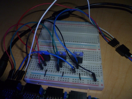
In order to connect my output signals to an RGB LED strip, I needed to run them through a power transistor. This is because each of the three output signals going into the LED strip can require more than 1 Amp that needs to sink to ground.
Here is what the setup looked like when I connected everything to my Nexys2 board:
Also, here are the results of the different colors being displayed on the RGB LED Strip:


Victor, I suggest you to use code in html format to shorten your post when you go to home page. It looks better for scrolling in home page.
LikeLiked by 1 person
140.on my post in 138.:After re-reading my comments, I feel that I was too harsh in my third paragraph. I think that it would be more fair to say instead: “I, for one, would not care if the opinions you offered were more constructive in nature. The problem is that your constant snippets, in which your offer little numerical analysis or tactical acumen, are ovnlihermwegly negative in tone.”As for personal attacks, there were none in my post.
LikeLike
Someone who actually knows about the Marshalls! I don’t come across that every day. Please tell me more about the SDA school–I’m sure we could “work it in” during our six-week trip. I went to your blog and am so fascinated by your story and so inspired by your faith. Six “instant” kids–wow!
LikeLike
Therese, I am aghast. Simply aghast. Well I may have been influential in causing you to read PRIDE AND PREJUDICE so I hope JANE EYRE will not be far behind.Like? 0
LikeLike